Views: 0 Author: Site Editor Publish Time: 2026-09-23 Origin: Site
Specifying an industrial shredder represents a high-stakes equipment decision for any material recovery facility. Selecting the wrong machine architecture guarantees catastrophic downtime, excessive wear on cutting components, and downstream processing failures. Facility operators face constant operational friction balancing raw volume reduction against precise size reduction. Bulky, unpredictable materials require aggressive handling, while secondary processing lines demand uniform, predictable output.
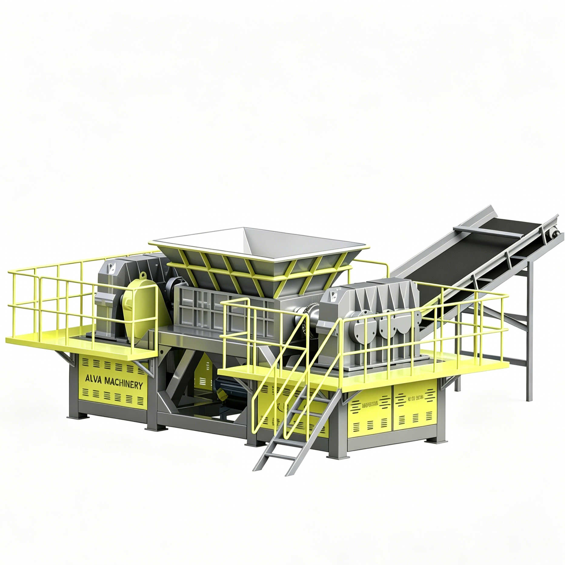
You solve this problem by understanding the fundamental engineering differences between available shredding technologies. Facility design hinges on this foundational choice. You must evaluate the mechanical capabilities of a Double Shaft Shredder against a Single Shaft Shredder. Twin-rotor machines excel at destroying massive, resistant items. Single-rotor machines deliver the exact particle sizes required for granulation or extrusion.
Mechanical Philosophy: A double shaft shredder operates on a low-speed, high-torque shearing principle ideal for bulky, mixed, or highly resistant materials, whereas a single shaft shredder utilizes higher speeds and a screen for precise, uniform particle reduction and faster processing of lighter materials.
Output Control: Single shaft shredders dictate exact output sizes via interchangeable screens; double shaft shredders produce coarse, variable-sized strips designed for primary volume reduction.
Material Suitability: Hard, hollow, or metal-contaminated materials (e-waste, tires, drums) require the aggressive bite of a double shaft shredder. Dense, rigid materials (plastics, wood blocks) or lighter materials requiring granulation preparation are better suited for single shaft systems.
TCO Implications: Maintenance profiles differ drastically—single shaft models require frequent screen clearing and pusher maintenance, while double shaft models require intensive blade hardfacing and shaft realignment over time.
Primary size reduction success depends entirely on machine architecture. The physical layout of the cutting chamber dictates material intake limits and determines how the machine handles physical resistance. You evaluate how rotors, blades, and feeding mechanisms interact with raw waste streams to prevent equipment failure. We break down the engineering principles driving both shredder types below.
A dual-shaft shredder relies on a low-speed, high-torque mechanism. The machine typically operates between 15 and 35 RPM. This slow rotation generates immense cutting force through heavy-duty planetary gearboxes. The architecture features two parallel, counter-rotating shafts. Engineers design these shafts with hexagonal or splined profiles to prevent the cutting discs from slipping under extreme loads.
Interlocking cutting discs slide onto these heavy-duty shafts. Spacers sit between the blades to create the precise cutting clearance required for shearing. The blades feature a staggered arrangement. This specific pattern optimizes the shearing force across the entire rotor length, preventing the motors from stalling when a dense object enters the chamber. The machine grabs the material using aggressive hooks machined directly into the blade profiles. The counter-rotating action pulls the waste downward into the cutting zone.
The reduction process involves shearing, tearing, and fracturing. As the interlocking blades pass each other, they slice the material. If the material resists shearing, the immense torque simply tears it apart. Brittle materials fracture under the compressive load. This architecture notably lacks a sizing screen. Output dimensions rely entirely on gravity and blade width. The machine discharges coarse, irregular strips directly through the bottom of the cutting chamber onto a discharge conveyor.
Stationary cleaning fingers mount to the shredder housing and extend between the cutting discs. These fingers scrape material out of the blade pockets as the shafts rotate. Without these cleaning fingers, elastic materials like rubber or plastic film would wrap around the spacers, eventually binding the shafts and destroying the main bearings.
A single-rotor shredder utilizes a medium-to-high-speed mechanism. The rotor typically spins between 70 and 120 RPM. This higher speed allows for faster processing of lighter materials and generates the kinetic energy needed for clean cuts. The cutting chamber features a single massive rotor equipped with multiple cutting tools. These rotary knives interact directly with stationary stator knives mounted to the machine frame.
The cutting action resembles a continuous scissor cut. The spinning rotor knives pass the fixed stator knives at tight tolerances, often gapped at less than a millimeter. This clean shearing action requires the material to stay engaged with the rotor. A hydraulic ram, or pusher, forces the material against the spinning cutting tools. Without this hydraulic pusher, materials would simply bounce around the hopper, riding on top of the spinning rotor without being cut.
A sizing screen mounts directly beneath the rotor in a heavy-duty cradle. This screen dictates the final particle size. Material remains in the cutting chamber until it is small enough to pass through the screen holes. The continuous interaction between the cutters, the stator knives, and the screen ensures a highly uniform output. This precise control makes the single-rotor machine indispensable for secondary processing preparation.
The hydraulic ram operates on a heavy-duty linear guide track. A dedicated hydraulic power unit supplies pressure to the ram cylinders. The machine's programmable logic controller continuously monitors the main rotor motor's amperage. When the rotor encounters a dense plastic block and the amperage spikes near the motor's maximum rating, the PLC instantly commands the hydraulic valves to retract the ram slightly. This relieves the pressure on the rotor, allowing it to regain RPM before the ram pushes the material forward again.
You categorize your waste streams accurately to match machine capabilities. Physical properties dictate shredder selection. Hardness, elasticity, density, and contamination levels all influence machine performance. We map specific material categories to the optimal shredding architecture to ensure continuous facility operation.
You need a twin-rotor machine for bulky, hollow, or highly elastic materials. Passenger tires, 55-gallon steel drums, and IBC totes require aggressive handling. The staggered hooks easily grab these large, awkward shapes. When a steel drum enters the hopper, the hooks pierce the metal, fold the drum inward, and pull it down through the interlocking blades. The slow rotation prevents elastic materials from bouncing away from the cutting zone.
This architecture excels at processing exceptionally hard or heavily contaminated waste. E-waste, municipal solid waste, and construction debris contain unpredictable elements. High torque prevents rotor jamming when encountering solid steel or dense aggregates. When processing e-waste like servers or printers, the low-speed shearing action breaks open the steel casings without generating excessive sparks or hazardous dust.
The counter-rotating blades create a self-feeding environment. Irregular shapes naturally pull down into the cutting chamber. You do not need a hydraulic ram to force the material into the blades. This makes the machine highly effective for mixed waste streams where material density varies wildly from batch to batch. Operators can dump entire loader buckets of mixed debris directly into the hopper without choking the machine.
You specify a single-rotor machine for dense, rigid, or thick-walled materials. Plastic purgings, wood pallets, paper rolls, and copper wire process beautifully in this architecture. The high-speed cutting action efficiently chips away at solid blocks. When a massive plastic purging block is pushed against the rotor, the individual cutters shave off small pieces until the entire block is reduced. Lighter materials also benefit from the higher rotation speeds, passing quickly through the cutting chamber.
Choose this machine when downstream processing requires a defined, homogenous fraction. Feeding an extruder or a secondary granulator demands uniform particle sizes. The internal screen guarantees this consistency. The hydraulic ram maintains constant pressure, ensuring a steady, predictable throughput rate that keeps downstream equipment fed at optimal capacity.
You must understand the limitations of this architecture. Single-rotor models struggle with highly elastic materials. Long plastic films or rubber strips can wrap around the high-speed rotor. This wrapping causes severe friction, melts the plastic onto the rotor body, and jams the machine. Heavy metal contaminants also pose a severe risk. A solid piece of steel entering the cutting chamber will cause catastrophic damage to the rotary knives, shatter the stator knives, and destroy the sizing screen.
Evaluating shredder technology requires mapping specific machine features to operational outcomes. You understand how internal components affect scalability and production compliance. We analyze output control, throughput dynamics, and the realities of wear part maintenance to guide equipment specification.
Technical Feature | Twin-Rotor Shredder | Single-Rotor Shredder |
|---|---|---|
Operating Speed | 15 - 35 RPM (Low Speed) | 70 - 120 RPM (Medium/High Speed) |
Torque Profile | Extremely High | Moderate |
Output Control | Blade Width (Coarse Strips) | Sizing Screen (Uniform Particles) |
Feed Mechanism | Self-Feeding (Gravity & Hooks) | Hydraulic Ram (Pusher) |
Primary Application | Volume Reduction / Pre-shredding | Size Reduction / Secondary Refinement |
Contamination Tolerance | High (Auto-reverse handles un-shreddables) | Low (Requires clean, sorted material) |
Output control defines the primary difference between these two machines. A single-rotor shredder delivers a highly predictable, screened output. You configure screens to produce particles ranging from 10mm to 50mm. The material cannot exit the cutting chamber until it meets this exact specification. This uniformity keeps downstream extruders and granulators running efficiently without surging.
A dual-shaft shredder produces a coarse, strip-like output. The final size usually ranges from 50mm to over 150mm. The width of the cutting blades determines the width of the shredded strip. The length of the strip remains variable, depending on how the material fractures. This irregular output serves perfectly for primary volume reduction, breaking open bales and destroying large items so they can be conveyed easily.
Output size directly impacts downstream sorting equipment. Optical sorters, eddy current separators, and magnetic belts require specific material profiles. Uniform particles spread evenly across high-speed conveyor belts. This allows near-infrared (NIR) sorting sensors to accurately identify and eject target materials using air jets. Coarse, tangled strips from a twin-rotor machine blind these sensors, bridge across sorting chutes, and drag non-target materials into the wrong bunkers.
Feed dynamics significantly impact overall throughput capacity. Batch feeding using a front-end loader creates massive surges in the cutting chamber. Continuous conveyor feeding provides a steady, manageable stream. You match your feeding method to the machine's intake capabilities to prevent bridging in the hopper.
The hydraulic ram in a single-rotor shredder actively regulates throughput. The programmable logic controller monitors rotor amperage. If the rotor works too hard, the ram retracts slightly. This intelligent feeding prevents overloads and maintains a consistent discharge rate. The machine processes material smoothly without constant operator intervention, maximizing the tons-per-hour output.
A twin-rotor shredder relies on the aggressive bite of the staggered blades. Hopper design plays a major role in directing material into the cutting zone. The machine handles massive surges well due to its high torque. Throughput fluctuates based on material composition. Dense, hard materials slow the shafts, while brittle materials shatter and pass through rapidly. Operators often install variable frequency drives to manage these load spikes and protect the electrical grid.
Maintenance lifecycles differ drastically between the two architectures. Single-rotor machines utilize square or circular cutting inserts machined from hardened tool steel. You bolt these cutters directly into the rotor pockets. When an edge wears down, maintenance teams unbolt the cutter, clean the pocket, rotate the insert 90 degrees to expose a fresh edge, and torque the bolt back to spec. This modular design allows for rapid wear part replacement directly on the factory floor.
Twin-rotor machines utilize custom-profiled cutting discs. These heavy-duty blades withstand immense physical abuse. Over thousands of operating hours, the aggressive hooks round off, and the cutting edges lose their sharp profile. The clearance gap between the interlocking blades widens, which degrades the shearing action and causes the machine to tear or fold material rather than cutting it cleanly.
Restoring these blades requires a massive maintenance overhaul. Technicians disconnect the drive trains, unbolt the bearing housings, and lift the entire shaft assemblies out of the cutting chamber using an overhead crane. The shafts are disassembled, and the worn blades undergo a specialized hardfacing process. Welders apply new hardened material onto the worn edges before CNC machining them back to original factory tolerances.
Integrating heavy shredding equipment into an active facility presents real-world challenges. You anticipate material variations and downstream bottlenecks during the design phase. Proper system design mitigates these risks before they cause catastrophic downtime. We outline strategies for managing contamination and designing multi-stage systems below.
Material contamination poses the greatest risk to shredder uptime. Un-shreddables frequently hide within bales of target material. A solid steel engine block hidden inside a baled car body or a massive steel plate mixed into construction debris will destroy cutting tools. You implement mechanical and software safeguards to protect the equipment.
Twin-rotor shredders utilize intelligent auto-reverse overload protection. When the shafts encounter an un-shreddable object, the electrical amperage spikes in milliseconds. The PLC instantly stops the shafts and reverses their rotation. This action frees the jammed object. The machine attempts to shred the object several times before shutting down and alerting the operator to manually remove the hazard.
Single-rotor shredders rely on mechanical safeguards. They feature mechanical clutches, fluid couplings, or shear pins integrated into the drive train. If a heavy metal contaminant enters the cutting chamber, the sudden impact breaks the shear pin or slips the clutch. This instantly disconnects the rotor from the gearbox. The sacrificial component prevents catastrophic damage to the expensive gearbox and motor.
Improper shredder integration causes severe downstream bottlenecking. Feeding coarse, irregular strips directly into a fine granulator destroys the granulator's rotor. You step down the material size gradually. Attempting to achieve a massive size reduction ratio in a single pass guarantees equipment failure and excessive heat generation.
We propose a common two-stage architecture for difficult materials. Use a twin-rotor shredder for primary volume reduction. This pre-shredding stage breaks open bales and destroys bulky items. Pass this coarse material under a suspended cross-belt magnetic separator to remove ferrous metals. Feed the clean, pre-shredded material into a single-rotor shredder for final, precise sizing.
Space constraints sometimes prohibit a two-stage system. In these cases, consider a four-shaft shredder. This hybrid alternative combines the high-torque bite of dual shafts with a sizing screen. Four-shaft machines utilize two primary cutting shafts and two secondary sizing shafts. This provides uniform sizing of difficult materials within a single, compact footprint, eliminating the need for extensive conveyor networks between machines.
Request physical material trials from original equipment manufacturers using your actual facility waste streams to verify machine capabilities.
Calculate your required continuous throughput in tons-per-hour, factoring in surge capacities and peak loading times to size the hopper correctly.
Evaluate the specific maintenance access of shortlisted models, focusing on screen removal times and blade rotation procedures to minimize planned downtime.
Design your facility layout to accommodate a two-stage reduction process, ensuring adequate space for magnetic separation between the primary and secondary shredders.
A: No. This architecture lacks a sizing screen. It relies entirely on the width of the cutting blades to dictate output. The machine produces coarse, irregular strips rather than uniform particles. The length of the output varies depending on how the material fractures during the shearing process.
A: Avoid processing highly elastic materials like long plastic films, ropes, or rubber strips. These materials wrap around the high-speed rotor and cause severe friction jams. You must also avoid heavily mixed waste containing massive metal contaminants, as these will shatter the rotary knives and destroy the sizing screen.
A: Generally, no. Twin-rotor models are inherently self-feeding. The counter-rotating shafts and aggressive blade hooks pull bulky materials down into the cutting zone using gravity and rotational force. Single-rotor models require the hydraulic pusher to maintain constant material contact against the spinning rotor.
A: Maintenance intervals depend entirely on material abrasiveness. Single-rotor inserts typically require rotation every few weeks, exposing a fresh edge quickly. Twin-rotor blades last much longer, often several months, but require intensive rebuilding, welding, and hardfacing when they finally wear down.
A: Power consumption profiles differ. Twin-rotor machines draw a continuous, high-torque electrical load to maintain their shearing force. Single-rotor machines experience fluctuating power loads. The amperage spikes significantly when the hydraulic ram engages and pushes dense material against the high-speed rotor.
A: Yes. This represents the industry standard for two-stage reduction. Facilities use the twin-rotor machine for primary breakdown and volume reduction. After removing metals with a magnet, they feed the coarse material into the single-rotor machine for secondary refinement and exact sizing.